


Fellows 48-12 Gear Shaper rebuild and CNC conversion w/30" Riser
Have one to sell?
ConditionUsed
1 available


IN STOCK, BUILDABLE TO MEET SPECIFICATIONS:
Inclusive of 30" Tall Riser!
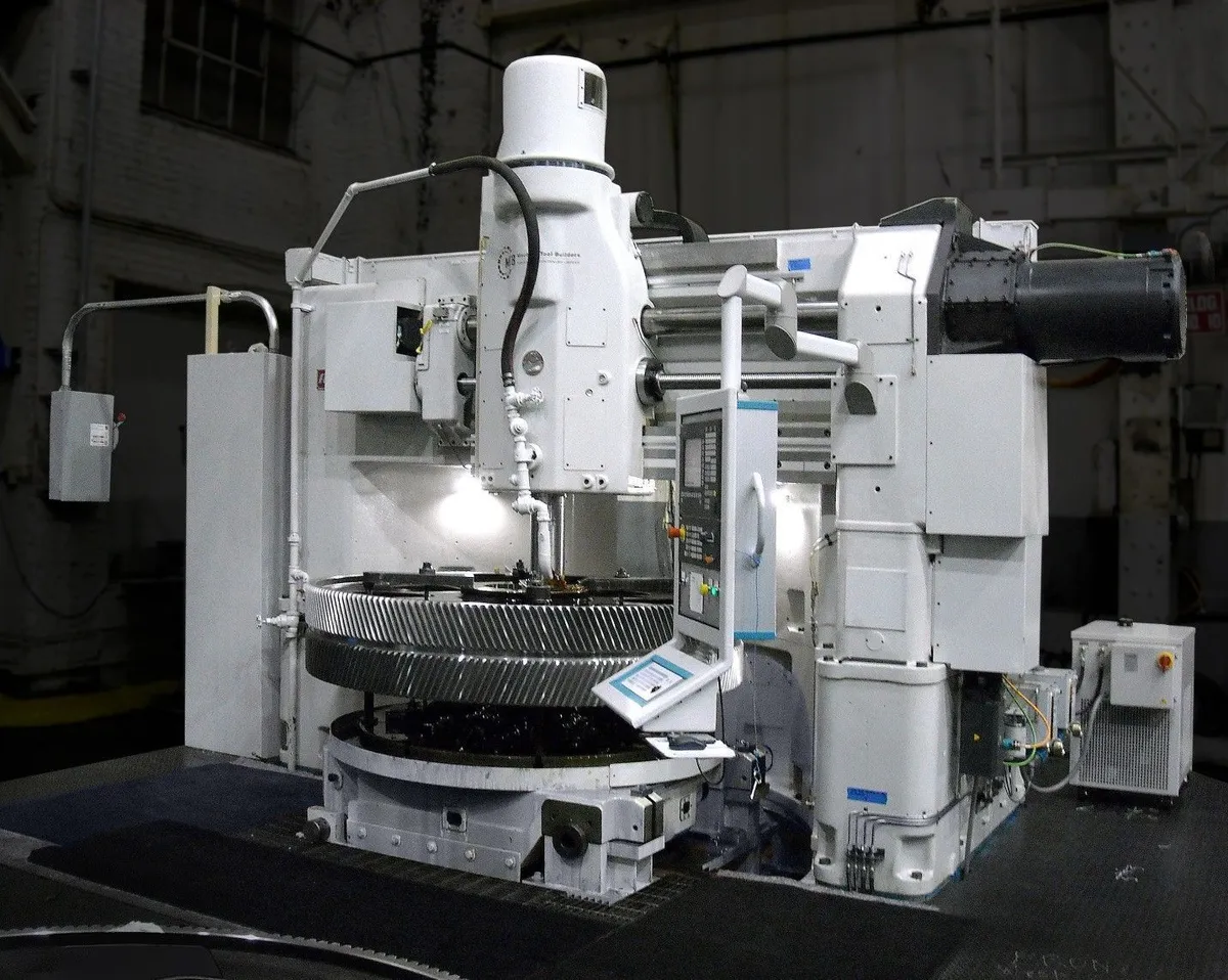
Machine Tool Builders is pleased to present this Fellows 48-12 gear shaping machine, an in-house stock platform slated to undergo a comprehensive rebuild and CNC conversion in our facility. This machine was originally selected because it represents the very best of the classic Fellows framework—exceptional mass, rigidity, and mechanical integrity—and because it's floor footprint is exceptionally small and efficient relative to the sizes of gears that can be produced with it.
Work on this machine began as a full rebuild with CNC conversion, but in mid-2023 it was intentionally paused as higher-priority customer programs moved through our shop. Rather than being rushed to completion, the machine was set aside in a known, controlled state; allowing us to resume the project with fresh eyes, current technology, and the benefit of additional engineering experience gained on similar conversions since that time. In short, this is a proven “carcass” with unfinished chapters still available to be written.
In its envisioned configuration, the machine is built as a fully CNC-controlled, 5-axis shaping platform, incorporating servo control of all primary motions: Radial (X), Stroke elevation and stroke length (Z), Cutter rotation (B), Worktable rotation (C), and the stroking spindle. The original mechanical drive systems are removed in their entirety and replaced with modern digital servomotors and drives, properly sized for torque, speed, and continuous duty cycle.
Stroke motion is driven through a large torque motor with an integrated safety brake mounted on the stroke rocker shaft, allowing complete CNC control of stroke position, length, and motion profile. The legacy crankshaft, associated gearing, and mechanical backoff cam system are eliminated. Backoff is instead executed through servo-controlled interpolation between the X and Z axes, providing precise, repeatable motion control while removing multiple historical wear points from the mechanical system.
The result is a cleaner, simpler mechanical architecture with significantly greater flexibility, improved dynamic response, and motion capability aligned with modern shaping strategies—while preserving the inherent mass, rigidity, and stability of the classic Fellows 48-12 platform.
Pursuing this expanded capability may also involve transitioning the control platform to Siemens One (instead of planned Fanuc 0iM-F), allowing us to leverage engineering, software, and motion strategies already proven on other recent MTB projects, including a Fellows 50-8 and an almost-complete Fellows 10-4. This reuse of validated architecture reduces technical risk while accelerating commissioning and long-term support.
Whether completed in its current CNC-enhanced configuration or advanced to a fully servo-controlled stroke system, the end result is a like-new, state-of-the-art Fellows 48-12 CNC gear shaper - delivering the performance and capability of a new machine at a fraction of the capital cost; and typically in far less time than sourcing new equipment.
Gear machinery rebuilds, CNC conversions, and modernization are MTB’s core competency, and this machine represents a rare opportunity to resurrect a heavyweight shaping platform and tailor it precisely to modern production needs.
This is not simply a rebuild. It is a second life: Engineered deliberately, executed carefully, and supported by a team whose business is gears, full stop.
Fellows 48-12 Vertical Gear Shaping Machine Rebuild & CNC Conversion:
Item General:
1 The machine is converted from a mechanical machine to a CNC machine during the complete rebuild.
2 The radial axis (X) is a CNC controlled axis.
3 New stroke drive (Z) for stroking rate, position and stroke length is a liquid cooled torque motor.
4 The cutter rotation axis (B) is a CNC controlled axis.
5 The worktable axis (C) is a CNC controlled axis.
6 The radial back off motion (X2) is a CNC controlled axis.
Cleaning:
7 Complete disassembly and cleaning of the machine.
General Mechanical:
8 Complete disassembly of the machine and inspection of all parts for wear.
9 Each pair of machine guide ways are refinished if required. All guideways are verified and adjusted if required to the original equipment specifications.
10 Engineer as required then manufacture and supply all motor adaptation flanges, couplings and pulleys.
11 Inspection and adjustment of the shaping spindle to the worktable for center alignment, and perpendicularity.
12 Replace worn out bearings and bushings.
13 Replacement of the radial acme screw with a new ball screw.
14 Mechanical systems which are no longer in use after the conversions to CNC are removed from the machine.
15 Stroking drive is equipped with Torque motor for infinitely variable stroking speed, quick return and programmable stroke position and length.
Shaping Head:
16 The head is fully disassembled, and all parts inspected for wear.
17 Guide assembly is fully inspected and rebuild as required.
18 Spindle bushing will be inspected and rebuild as required.
19 Shaping head will be fully re-assembled with the proper lash set on the worm drive.
20 All seals are replaced.
21 All bearings are replaced.
22 All bushings are replaced.
Worktable:
23 The worktable is removed from the machine.
24 Worktable is fully disassembled, cleaned and inspected.
25 Final drive gears (index worms or bull gears) are inspected for index accuracy.
26 All sealing surfaces are repaired.
27 All seals are replaced.
28 Table way surfaces are refinished to reduce surface area and promote good lubrication.
29 Tabletop surface is inspected and re-machined as required. Minus material sections will be left as is.
30 The table is fully re-assembled with the proper lash set.
31 All bearings are replaced.
Stroke Drive:
38 All assemblies fully disassembled, and all parts inspected for wear.
39 All worn parts were either repaired or replaced.
40 All bushings are replaced with OEM or equivalent.
41 All seals are replaced with OEM or equivalent.
42 All bearings are replaced with OEM or equivalent.
Guarding:
43 MTB will install guarding for any pinch points, rotating elements, hot surfaces and other hazardous machine elements.
44 MTB will straighten, repair and reuse any existing guarding for the machine.
Lubrication:
45 Installation of new progressive lubrication valves, pumps, meter blocks, hoses and feedback sensors.
46 New pipes will be installed.
47 New distribution manifolds will be installed.
48 All pressure gauges or electronic pressure sensors will be labeled with proper pressure settings.
49 All filters will have differential pressure sensors or gauges to detect dirty filter conditions.
50 All fluid reservoir points shall be labeled with the type of fluid and will be equipped with visual sight glass for low and high levels.
Coolant:
51 MTB will supply new coolant motor.
Chip Extraction:
52 MTB will provide the Fellows standard chip basket.
Electrical:
53 A new electrical cabinet is installed with all new equipment inside. IEC devices along with circuit breakers are used.
54 A new operator pendant box is installed from a new arm. It will include the CRT, Keyboard and Machine operation panel mounted inside.
55 All electrical prints and parts lists are drawn with AutoCAD Electrical.
56 All new servo motor power and feedback cables are provided.
57 A new spindle motor power and feedback cables is provided.
58 Auxiliary cabinet lighting and programming terminal power will be supplied.
59 Installation of all new machine wiring.
60 All axis positions will be measured from the motor encoder feedback.
61 Cabinet will remain in the current location but will rest on the floor.
62 Electrical Cabinet will be air conditioned.
63 MTB will provide all wire, tags, conduit, flex and other miscellaneous equipment required to complete the installation per NFPA codes.
64 New cabling to the operator station or pendant are installed.
65 Power requirements is 460VAC, 60Hz. Power figures will be available after the electrical engineering is completed.
Controls:
66 Siemens CNC 840D with horizontally arranged color display and machine operator's panel. Siemens digital axes drives and motors.
67 Fanuc CNC 0iMF and Alpha Series HVi digital drives and motors instead of Siemens on request at NO ADDITIONAL CHARGE.
Notation - Shaping Software:
68 Conversational based platform within the CNC.
69 Up to four sequential surfaces with elevation setting under CNC control.
70 Up to five cuts per cycle.
71 Spiral or Plunge infeed cycle.
72 Programmable rotary dwell.
73 Digressive infeed feed rate.
74 Inch / Metric switchable.
75 Spiral out of cut.
76 M and G code programming is allowed with conversational programming present.
77 Multiple program storage and retrieval.
78 Quick recut cycle.
79 Programmable stroke positions, stoke length and speed.
80 Automatic cutter indexing.
81 Orientation of cutter and workpiece.
82 Programmable Quick return of stroke.
83 Slotting capability.
General Software:
84 MTB will provide a fully commented ladder logic program to control the machine with.
85 MTB will provide machine diagnostic error messages for all the machine related functions like fluid levels, pressures, faults, interlocks etc.
Painting:
86 The machine, electrical cabinet and guarding are completely refinished and painted MTB gray.
Documentation in digital format:
87 All mechanical prints for changes which MTB makes during the recontrol / retrofit / rebuild.
88 All copies of spare parts and service manuals for equipment supplied by MTB.
89 All copies of the MTB operator's Instruction manuals.
90 All copies of the MTB programmer’s manuals.
91 All copies of the PLC logic interface program and backup CDROM.
92 All copies of the new electrical / hydraulic / lubrication / pneumatic / coolant system drawings.
Run Off:
93 MTB will provide support for the initial machine startup and test running at our standard rates.
Training:
94 MTB will supply 5 days of operator training at the completion of the installation at our standard rates.
Build Specifications:
95 Electrical, mechanical, hydraulic, pneumatic and safety systems are installed in accordance with all applicable customer specifications, and ISO, IEEE, ANSI, DIN and NFPA standards.
96 Alignments are verified by using the original Fellows alignment specification.
Controls Options:
A Euchner hand pendant, no display, with axis selection, handwheel, jogging, E-Stop and dead man buttons.
We use cookies to improve your experience. Privacy Policy.