


FELLOWS FS180 Hydrostroke
Have one to sell?
ConditionUsed
1 available


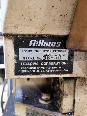


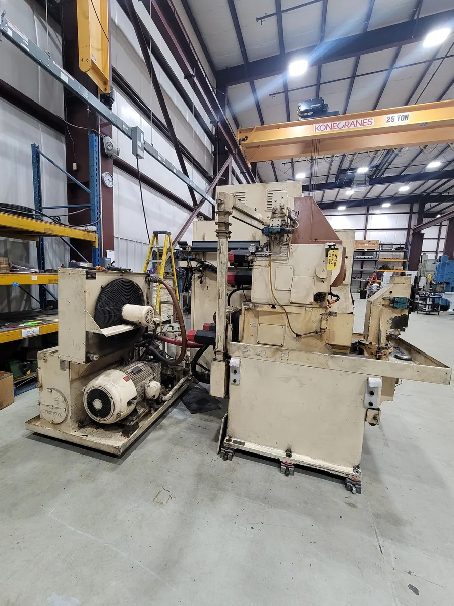
This machine is an original Fellows FS180 Hydrostroke Gear Shaper, Equipped with the Fanuc 15MA CNC, Conversational Programming and Fanuc Digital Servo Drives. The machine will be re-controlled with a new Fanuc 0iMF Plus CNC to make it very modern and supportable. The full conversion requires about 3-4 months to complete. Once finished there will a completely new electrical panel with all new equipment inside. Most if not all the old machine wiring will be replaced along with many of the machine mounted sensors and active components like valves, switches etc. All new Fanuc Alpha HVi servo drives will be installed along with all new feedback systems from Fanuc and Heidenhain.
I. MACHINE SPECIFICATIONS:
• Maximum workpiece diameter: 7.08” / 179.8 mm
• Maximum stroke length: 1.5” / 38.1 mm
• Maximum face width: 1.25" / 31.75mm
• Maximum Diametral pitch (spur): 6.3DP / 4.02 Module
• Maximum strokes per minute: 1,700 SPM
• Maximum center distance workpiece/tool: 6.3” / 160.02 mm
• Minimum center distance 2.76" / 70 mm
• Maximum cutter diameter 6" / 152mm
• Bore through work spindle: 4.33” / 110 mm
• RS-232 port or up/down loading programs.
• PCMCIA port for up/down loading programs.
II. MACHINE REBUILD FEATURES:
Item GENERAL
1). All work will be done at Machine Tool Builders facility located in Machesney Park, IL.
2). The machine(s) will be recontrolled.
3). The spindle speed will be controlled through a new spindle drive and spindle motor.
4). The radial axis (X) .
5). The cutter rotation axis (B) will become a CNC controlled axis.
6). The worktable axis (C) will become a CNC controlled axis.
7). The stroke length will remain a manual adjustment.
CLEANING
8). Machine will be cleaned before the start of the recontrol program.
GENERAL MECHANICAL
9). Mechanical systems which are no longer in use after the conversions to CNC will be removed from the machine.
10). Engineer as required then manufacture and supply all motor adaptation flanges, couplings and pulleys.
11). Remove old servo motors and install new servo motors.
12). Remove old spindle motor and install new spindle motor.
13). Standard Chip collection is done with a catch basket.
GUARDING
14). All guarding will be returned to its original configuration and function at the time the rebuild started unless otherwise noted.
ELECTRICAL
15). A new electrical cabinet will be installed with all new equipment inside. IEC devices along with circuit breakers will be used wherever possible.
16). A new operator’s station will be installed where the current one is. It will include the CRT, Keyboard and Machine operation panel mounted inside.
17). Installation of all new machine wiring.
18). MTB will provide all wire, tags, conduit, flex and other miscellaneous equipment required to complete the installation per NFPA codes.
19). All electrical prints and parts lists will be drawn with AutoCAD Electrical.
20). All new servo motor power and feedback cables will be run for only the replaced servos on the machine.
21). All new secondary encoder cabling will be run for only the replaced servos on the machine.
22). New cabling to the operator’s station or pendant will be run.
23). Unless otherwise stated all axes will be measured from absolute encoders within the servo motors.
24). Reuse any electrical cabinets, duct way and junction boxes that are practical to reuse, unusable ones will be replaced with new.
25). Power requirements will be 460VAC; 60Hz. Power figures will be available after the electrical engineering is completed.
CONTROLS
26). Fanuc 0i-MD CNC with 10.4" horizontally arranged color display and machine operator's panel.
27). Fanuc Alpha iS HV digital axes drive(s) and motor(s).
28). ATTENTION - If your plant power system is not a wye scheme with grounded center point, you will require an isolation transformer for these new drives.
SHAPING SOFTWARE
29). Conversational based platform within the CNC.
30). Up to four sequential surfaces (Only practical if elevation setting is under CNC control).
31). Up to five cuts per cycle.
32). Spiral or Plunge infeed cycle.
33). Programmable rotary dwell.
34). Digressive infeed feedrate.
35). Inch / Metric switchable.
36). Spiral out of cut.
37). M and G code programming is allowed with conversational programming present.
38). Multiple program storage and retrieval.
39). Quick recut cycle.
40). Automatic cutter indexing (Requires independent cutter 'B' and worktable 'C' axes).
41). Orientation of cutter and workpiece (Requires independent cutter 'B' and worktable 'C' axes).
PAINTING
42). The machine and guarding will be completely repainted. Paint color will be MTB white unless you specify a special color.
DOCUMENTATION
43). Two (2) copies of the wiring diagrams on 11x17 paper.
44). Two (2) copies of the MTB operators Instruction manuals.
45). Two (2) copies of spare parts and service manuals for equipment supplied by MTB.
46). Two (2) copies of the PLC logic interface program and backup CDROM.
47). Two (2) copies of any mechanical prints for changes which MTB makes during the recontrol / retrofit / rebuild process.
INSTALLATION & RUN-OFF
48). Installation, runoff and training at your facility.
TRAINING
49). MTB will supply 2 days of operator training at the completion of the installation.
50). MTB will supply 1 day of maintenance training at the completion of the installation.
BUILD SPECIFICATIONS
51). Electrical, mechanical, hydraulic, pneumatic and safety systems will be installed in accordance with all applicable customer specifications, and ISO, IEEE, ANSI, DIN and NFPA standards.
We use cookies to improve your experience. Privacy Policy.