


Used FELLOWS 10-4 REMANUFACTURED CNC | Gear Shapers
Have one to sell?
ConditionUsed
1 available


Machine Tool Builders is pleased to offer one rebuilt and CNC controlled Fellows 10-4 gear shaper. As part of the remanufacture MTB will repair and/or replace the following mechanical and electrical items: All seals, gaskets, ball screws, wiring (machine and cabinet), broken or bent guarding, hoses, bearings, piping, lubrication systems, coolant systems, hydraulic and/or pneumatic valves, pressure switches, float switches, proximity switches, AC motors, pumps, filters, limit switches, buttons, lamps and indicators, refinish all linear guide ways and replace all way wipers. MTB will inspect all internal gearing, shafts, castings, table, stroke guide, stroke mechanism, worktable and cutter rotation drive trains, and back off cam assembly. The elevation and stroke length adjustments will remain manual adjustments.
The recontrol MTB is proposing will replace the existing system with a Fanuc 0i-MD CNC. MTB will also be replacing the entire electrical cabinet and all the equipment and wiring inside of the electrical cabinet with new equivalents. This includes all motor starters, relays, power supplies, terminal strips, fuses etc. The machine will be converted to a 3 axis and single spindle CNC controlled machine. The existing mechanical drive systems will be replaced by new Fanuc Alpha iS HV digital servomotors and drives of the proper torque and speed. The spindle system will be controlled by a new Fanuc Alpha series spindle drive system. MTB will include as part of the recontrol, our conversational programming which will provide your operators with menu driven part and process information on the CNC operator’s panel. This allows ease of entry of the gear data by the operator.
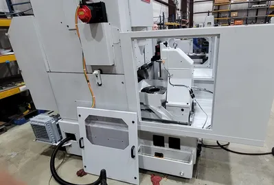
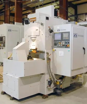
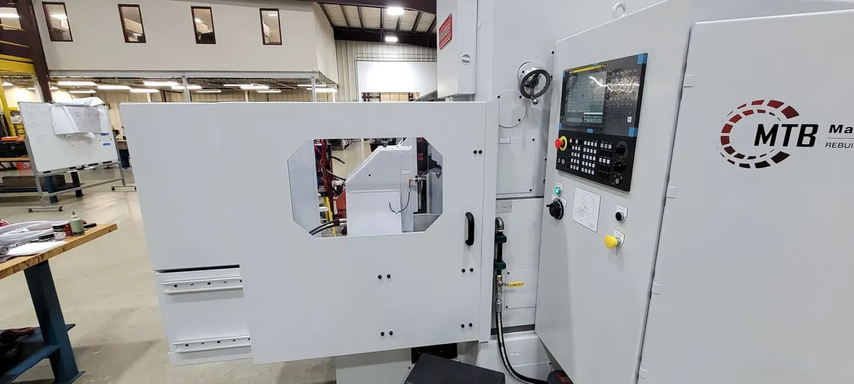
The pictures herein represent the machine currently in build. The pictures of a complete machine are representative of type only - having been the last machine we completed in late 2025. More pictures will be posted as the rebuilding process progresses. Expected completion of the machine is slated for end of May / Early June, 2026.
We appreciate your considering Machine Tool Builders, Inc. for this project. If you have any questions regarding this quote, please feel free to contact us anytime.
Fellows 10-4 Shaping Machine Re-Control & Rebuild Program - 3 Axes of CNC Control.
I. MACHINE SPECIFICATIONS:
• Maximum workpiece diameter: 10” / 254 mm
• Maximum stroke length: 4” / 102mm (See Below for Add'l Options)
• Maximum Diametral pitch (spur): 4DP / 6.35 Module
• Maximum Diametral pitch (helical): 5DP / 5.08 Module
• Maximum strokes per minute: 750 SPM / 1,200 SPM (Optional)
• Maximum center distance workpiece/tool: 14” / 355.6 mm
• Distance between worktable and cutter: 13.0” / 320.2 mm
• Bore through work spindle: 5.875” / 149.225 mm
• Cutter spindle diameter: 3.543” / 89.998 mm
• Fanuc α15/7000 HVi spindle motor: 20 HP / 15 kW
• Rapid traverse rates:
- X axis: 118 in/min / 3000 mm/min
- B axis: 40 RPM / 14,400 deg/min
- C axis: 40 RPM / 14,400 deg/min
• Linear axis resolution: .0001” / .001mm
• Rotary axis resolution: .001° / .001°
• Plant power requirement: 460V 60Hz 3-Phase
• RS-232 port or up/down loading programs.
• PCMCIA port for up/down loading programs.
II. MACHINE REBUILD FEATURES:
Item GENERAL
1). All work will be done at Machine Tool Builders facility located in Machesney Park, IL.
2). The machine(s) will be completely rebuilt.
3). The spindle speed will be controlled through a new spindle drive and spindle motor.
4). The radial axis (X) will become a CNC controlled axis.
5). The cutter rotation axis (B) will become a CNC controlled axis.
6). The worktable axis (C) will become a CNC controlled axis.
7). The elevation will remain a manual adjustment.
8). The stroke length will remain a manual adjustment - OPTION AVAILABLE.
CLEANING:
9). Machine will be cleaned before the start of the rebuild.
10). Complete disassembly and cleaning of the machine.
GENERAL MECHANICAL:
11). Complete disassembly of the machine and inspection of all parts for wear.
12). Inspection of all major components for wear. Replacement or repair of the worn components as required. (Index and hob head final drive gear sets are excluded).
13). Each pair of machine guide ways will be refinished if required. All guideways will be verified and adjusted if required to be as close as possible to the original equipment specifications.
14). Installation of new Turcite material on the column underside to restore proper alignment with drive shaft and screw.
15). Mechanical systems which are no longer in use after the conversions to CNC will be removed from the machine.
16). Radial ballscrew will be rebuilt or replaced.
17). Radial guideways will be removed and reground.
18). Radial slide gibs will be reset.
19). Engineer as required then manufacture and supply all motor adaptation flanges, couplings and pulleys.
20). Remove old servo motors and install new servo motors.
21). Remove old spindle motor and install new spindle motor.
22). Replace worn out bearings and bushings.
23). Replacement of all seals with repair of all damaged sealing surfaces.
SHAPING HEAD:
24). Shaping head to be fully disassembled and parts inspected for wear.
25). Inspection of guides.
26). All bearings will be replaced with OEM or equivalent.
27). All bushings will be replaced.
28). All seals will be replaced with OEM or equivalent.
29). Shaping head will be fully re-assembled with the proper lash set on the worm drive.
WORKTABLE:
30). Worktable will be fully disassembled, cleaned and inspected.
31). The worm and worm wheel will be replaced or repaired if required.
32). All bearings will be replaced with OEM or equivalent.
33). All sealing surfaces will be repaired.
34). All seals will be replaced with OEM or equivalent.
35). Table top surface will be reground. Minus material sections will be left as-is.
36). The table will be fully re-assembled with the proper lash set*.
(*Provided the worm wheel is not worn out, and the worm is adjustable)
STROKE DRIVE/ELEVATION/LENGTH ASSEMBLIES:
37). All assemblies will be fully disassembled, and all parts inspected for wear.
38). All bearings will be replaced with OEM or equivalent.
39). All bushings will be replaced.
40). All seals will be replaced with OEM or equivalent.
41). All worn parts will be either repaired or replaced as required.
HYDRAULIC:
42). Installation of new or rebuilt hydraulic pumps, hoses, valves, pressure switches, pressure reducing valves, flow controls and pressure regulators. Piping will be re-used if not bent.
43). Manifolds will be reused if they are in good condition and applicable.
44). MTB will either rebuild or replace the hydraulic motor(s).
45). Pipes will be reused if they are in good condition and applicable.
46). Power clamping base will be rebuilt or replaced.
LUBRICATION:
47). Installation of new lubrication valves, pumps, meter blocks, hoses and feedback sensors.
48). Manifolds will be reused if they are in good condition and applicable.
49). MTB will either rebuild or replace the lubrication system motor(s).
50). New lubrication lines will be run to the ballscrew nuts and bearings.
51). Pipes will be reused if they are in good condition and applicable.
COOLANT:
52). MTB will either rebuild or replace the coolant system motor(s).
53). Replace and/or repair all coolant components such as pumps, motor, hoses and nozzle(s).
CHIP EXTRACTION:
54). Standard Chip collection is done with a catch basket.
GUARDING:
55). All guarding will be returned to its original configuration and function at the time the rebuild started unless otherwise noted.
ELECTRICAL:
56). A new electrical cabinet will be installed with all new equipment inside. IEC devices along with circuit breakers will be used wherever possible.
57). A new operator’s station will be installed where the current one is. It will include the CRT, Keyboard and Machine operation panel mounted inside.
58). Installation of all new machine wiring.
59). MTB will provide all wire, tags, conduit, flex and other miscellaneous equipment required to complete the installation per NFPA codes.
60). All electrical prints and parts lists will be drawn with AutoCAD Electrical.
61). All new servo motor power and feedback cables will be run for only the replaced servos on the machine.
62). All new secondary encoder cabling will be run for only the replaced servos on the machine.
63). New cabling to the operator’s station or pendant will be run.
64). Unless otherwise stated all axes will be measured from absolute encoders within the servo motors.
65). Reuse any electrical cabinets, duct way and junction boxes that are practical to reuse, unusable ones will be replaced with new.
66). Power requirements will be 460VAC; 60Hz. Power figures will be available after the electrical engineering is completed.
III. ELECTRICAL & SOFTWARE:
CONTROLS:
67). Fanuc 0i-F+ CNC with 10.4" horizontally arranged color display and machine operator's panel.
68). Fanuc Alpha iS HV digital axes drive(s) and motor(s).
69). ATTENTION - If your plant power system is not a wye scheme with grounded center point, you will require an isolation transformer for these new drives.
SHAPING SOFTWARE:
70). Conversational based platform within the CNC.
71). Up to four sequential surfaces (Only practical if elevation setting is under CNC control).
72). Up to five cuts per cycle.
73). Spiral or Plunge infeed cycle.
74). Programmable rotary dwell.
75). Digressive infeed feedrate.
76). Inch / Metric switchable.
77). Spiral out of cut.
78). M and G code programming is allowed with conversational programming present.
79). Multiple program storage and retrieval.
80). Quick recut cycle - allows the operator to bring the workpiece into size without changing the programming parameters.
81). Auxiliary function selection (tailstock/clamping seq.).
82). Automatic cutter indexing (Requires independent cutter 'B' and worktable 'C' axes).
83). Orientation of cutter and workpiece (Requires independent cutter 'B' and worktable 'C' axes).
84). Clamp avoidance (Requires independent cutter 'B' and worktable 'C' axes).
85). Slotting capability (Requires independent cutter 'B' and worktable 'C' axes).
PAINTING:
86). The machine and guarding will be completely repainted. Paint color will be MTB white unless you specify a special color.
DOCUMENTATION:
87). Two (2) copies of the wiring diagrams on 11x17 paper.
88). Two (2) copies of the MTB operators Instruction manuals.
89). Two (2) copies of spare parts and service manuals for equipment supplied by MTB.
90). Two (2) copies of the PLC logic interface program and backup CDROM.
91). Two (2) copies of any mechanical prints for changes which MTB makes during the recontrol / retrofit / rebuild process.
INSTALLATION & RUN-OFF:
92). Installation, runoff and training at your facility.
TRAINING:
93). MTB will supply 2 days of operator training at the completion of the installation.
94). MTB will supply 1 day of maintenance training at the completion of the installation.
BUILD SPECIFICATIONS:
95). Electrical, mechanical, hydraulic, pneumatic and safety systems will be installed in accordance with all applicable customer specifications, and ISO, IEEE, ANSI, DIN and NFPA standards.
IV. OPTIONAL EQUIPMENT:
- Custom risers available - on request.
- 3" Add'l Height.
- 6" Add'l Height.
- 7" Add'l Height.
- 12" Add'l Height.
- Multiple Tailstock Options (Customer to Specify):
- Weldment type; Removeable, with Hydraulically actuated Tailstock Center.
- Retractable Type; Retracts to & from table w/Hyd. actuated Tailstock Center.
- Swing-Away Type; with Hydraulically actuated Center.
- Full Enclosure - Note that Enclosure will differ based upon presence of tailstock chosen (above).
- 5" / 6" Stroke Length
- 2" of True Cutter Positioning
- Tilting Table with 10 degrees of angle adjustment.
- Face Gear Attachment options available.
- Hydraulic Work Clamping.
MTB's shaping conversation software for gear shapers is a Macro Executor based program running from the SRAM memory on the Fanuc CNC. The programming environment is made very user friendly through built-in help screens and helpful prompts. After entering the data for each respective item, you then create a program by selecting a cutter, a workpiece and a process from the items in the library. A program can consist of up to four surfaces that you want to cut.
Please see "Additional Photos" below for details on the HMI Screens.
We use cookies to improve your experience. Privacy Policy.