

Used FELLOWS 20-4 remanufactured | Gear Shapers
Have one to sell?
ConditionUsed
1 available

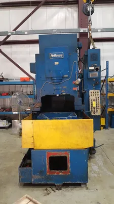


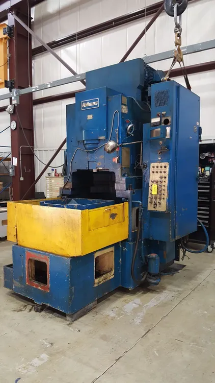
Machine Tool Builders is pleased to offer one rebuilt and CNC controlled Fellows 20-4 gear shaper. As part of the remanufacture MTB will repair and/or replace the following mechanical and electrical items: All seals, gaskets, ball screws, wiring (machine and cabinet), broken or bent guarding, hoses, bearings, piping, lubrication systems, coolant systems, hydraulic and/or pneumatic valves, pressure switches, float switches, proximity switches, AC motors, pumps, filters, limit switches, buttons, lamps and indicators, refinish all linear guide ways and replace all way wipers. MTB will inspect all internal gearing, shafts, castings, table, stroke guide, stroke mechanism, worktable and cutter rotation drive trains, and back off cam assembly. The elevation and stroke length adjustments will remain manual adjustments.
The recontrol MTB is proposing will replace the existing system with a Fanuc 0i-MD CNC. MTB will also be replacing the entire electrical cabinet and all the equipment and wiring inside of the electrical cabinet with new equivalents. This includes all motor starters, relays, power supplies, terminal strips, fuses etc. The machine will be converted to a 3 axis and single spindle CNC controlled machine. The existing mechanical drive systems will be replaced by new Fanuc Alpha iS HV digital servomotors and drives of the proper torque and speed. The spindle system will be controlled by a new Fanuc Alpha series spindle drive system. MTB will include as part of the recontrol, our conversational programming which will provide your operators with menu driven part and process information on the CNC operator’s panel. This allows ease of entry of the gear data by the operator.
We appreciate your considering Machine Tool Builders, Inc. for this project. If you have any questions regarding this quote, please feel free to contact us anytime.
I. Machine Specifications:
Pitch rating 5 DP 5.08 Mod
Maximum workpiece diameter (External) 20 in 508 mm
Maximum workpiece diameter (Internal) 20 in 508 mm
Worktable diameter 19.7 in 500 mm
Table bore diameter 9 in 230 mm
Maximum face-width 4 in 101.6 mm
Stroking speed range 50 to 1300 RPM
Spindle Power 20 HP 15 kW
Rapid traverse radial 78.74 in/min 2000 mm/min
Rapid traverse speed of cutter 5400 deg/min 15 RPM
Rapid traverse speed of table 5400 deg/min 15 RPM
Machine Weight 18000 lbs 8180 kg
Plant power 460 VAC 60 Hz
Length 96 in 2440 mm
Width 78 in 1980 mm
Height (No riser) 108 in 2743 mm
II. Machine Rebuild Features:
Item General
1 All work to be completed at Machine Tool Builders’ facility in Machesney Park, IL.
2 The machine(s) will be fully rebuilt
3 The spindle speed controlled through a new spindle drive and spindle motor.
4 The radial axis (X) is CNC controlled axis.
5 The cutter rotation axis (B) is CNC controlled axis.
6 The worktable axis (C) is CNC controlled axis.
7 The elevation remains manual adjustment.
8 The stroke length remains manual adjustment.
Cleaning
9 Machine cleaned before the start of the reconditioning
10 Complete disassembly and cleaning of the machine.
General Mechanical
11 Meticulous disassembly and inspection of the machine and all parts for wear and full reconditioning as required.
12 MTB will replace or rebuild/relace worn components as required.
13 The machine guide ways will be inspected. All guideways verified, to be as close as possible to the original equipment specifications.
15 Mechanical systems, no longer in use after conversion to CNC are removed from the machine.
16 Radial in-feed cylinder replaced with a ballscrew
18 Radial slide gibs reset
19 Engineered, manufactured and supplied of all motor adaptation flanges, couplings and pulleys.
20 Removal of old servo motors and installation of new servo motors.
21 Removal of old spindle motor and installation new spindle motor.
22 Replacement of worn-out bearings and bushings.
23 Replacement of all seals and repair of all damaged sealing surfaces.
Shaping Head
24 Shaping head to be fully disassembled and parts inspected for wear
25 Inspection of guide, if guide found to be damaged or replacement is needed MTB will contact customer to determine best course of action.
26 All bearings replaced with OEM or equivalent.
27 All worn bushings replaced with OEM or equivalent.
28 All seals replaced with OEM or equivalent.
29 Shaping head will be fully re-assembled with the proper lash set on the worm drive.
Upper worm and worm wheel. Possible additional costs Note MTB will fully inspect items if found to be completely unserviceable MTB will notify customer accordingly and a proper course of action can be determined.
Worktable
30 Worktable fully disassembled, cleaned and inspected.
31 Worm and worm wheel. Possible additional costs Note MTB will fully inspect items if found to be completely unserviceable MTB will notify customer accordingly and a proper course of action can be determined.
32 All worn bearings are replaced with OEM or equivalent.
33 All sealing surfaces will be repaired.
34 All seals to be replaced with OEM or equivalent.
35 Tabletop surface will be inspected
36 The table will be fully re-assembled with the proper lash set.
Stroke Drive/Elevation/Length Assemblies
37 All assemblies will be fully disassembled, and all parts inspected for wear.
38 All worn parts will be either reconditioning
39 All worn bushings replaced with OEM or equivalent.
40 All seals replaced with OEM or equivalent.
41 All bearings replaced with OEM or equivalent.
Hydraulic
42 Reconditioning of hydraulic pumps, hoses, valves, pressure switches, pressure reducing valves, flow controls and pressure regulators.
43 Manifolds to be reused if they were in good condition.
44 MTB will either rebuild or replace the hydraulic motor(s).
45 Pipes reused if they were in good condition.
Lubrication
47 Lubrication valves, pumps, meter blocks, hoses and feedback sensors will be reconditioning
48 Manifolds reused if they were in good condition
49 MTB will test the lubrication system
50 New lubrication lines as required
51 Pipes to be reused if in good condition
Coolant
52 MTB will control the coolant system motor with the new CNC
53 Inspect and/or repair/or replace all coolant components such as pump, motor, hoses and nozzle
Chip Extraction
54 Chip collection will be inspected.
Guarding
56 All guarding to be returned to its original configuration and function.
Electrical
57 New electrical cabinet installation with all new equipment inside. IEC devices, along with circuit breakers installed.
58 A new operator’s station installed. It includes the CRT, Keyboard and Machine operation panel mounted inside.
59 All new machine wiring with installation
60 MTB to provide all wire, tags, conduit, flex and other miscellaneous equipment required to complete the installation per NFPA codes.
61 All electrical prints and parts lists are drawn with AutoCAD Electrical.
62 All new servo motor power and feedback cables run on the machine.
63 All new secondary encoder cabling run on the machine.
64 New cabling to the operator’s station or pendant run on the machine.
65 Unless otherwise stated all axes measured from absolute encoders within the servo motors.
66 Power requirements are 460VAC, 60Hz.
67 Power figures are available from electrical engineering.
Controls
68 Fanuc 0i-MF CNC with horizontally arranged color display and machine operator's panel.
69 Fanuc Alpha HVi digital axes drive(s) and motor(s).
70 ATTENTION - If your plant power system is not a wye scheme with grounded center point, you will require an isolation transformer for these new drives.
Shaping Software
71 Conversational based platform within the CNC
72 Up to four sequential surfaces (Only practical if elevation setting is under CNC control)
73 Up to five cuts per cycle
74 Spiral or Plunge infeed cycle
75 Programmable rotary dwell
76 Digressive infeed feed rate
77 Inch / Metric switchable
78 Spiral out of cut
79 M and G code programming is allowed with conversational programming present.
80 Multiple program storage and retrieval
81 Quick recut cycle
82 Auxiliary function selection (tailstock/clamping seq.)
83 Automatic cutter indexing (Requires independent cutter 'B' and worktable 'C' axes)
84 Orientation of cutter and workpiece (Requires independent cutter 'B' and worktable 'C' axes)
85 Clamp avoidance (Requires independent cutter 'B' and worktable 'C' axes)
86 Slotting capability (Requires independent cutter 'B' and worktable 'C' axes)
Painting
87 The machine and guarding are completely repainted. Paint color is MTB white.
Documentation
88 Two (2) copies of the wiring diagrams on 11x17 paper
89 Two (2) copies of the MTB operators Instruction manuals
90 Two (2) copies of spare parts and service manuals for equipment supplied by MTB
91 Two (2) copies of the PLC logic interface program and backup CDROM
92 Two (2) copies of any mechanical prints for changes which MTB makes during the recontrol / retrofit / rebuild
Installation and Run Off
93 Installation, runoff and training at your facility
Training
94 MTB will supply operator training at the completion of the installation
Build Specifications
96 Electrical, mechanical, hydraulic, pneumatic and safety systems will be installed in accordance with all applicable customer specifications, and ISO, IEEE, ANSI, DIN and NFPA standards
MTB's shaping conversation software for gear shapers is a Macro Executor based program running from the SRAM memory on the Fanuc CNC. The programming environment is made very user friendly through built-in help screens and helpful prompts. After entering the data for each respective item, you then create a program by selecting a cutter, a workpiece and a process from the items in the library. A program can consist of up to four surfaces that you want to cut.
Please see "Additional Photos" below for details on the HMI Screens.
We use cookies to improve your experience. Privacy Policy.