


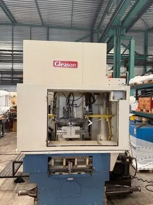
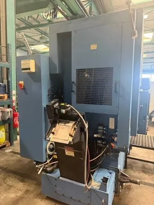
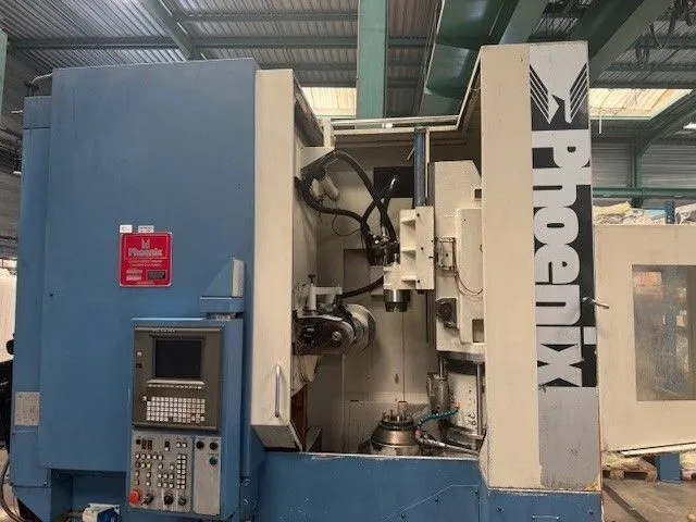
1997 GLEASON PHOENIX 400GH - Recontroled & Recertified
Have one to sell?
ConditionUsed
1 available

Gleason 400GH 'recontrol' & 'recertification' program.
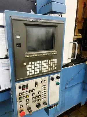
The machine will be equipped with a FANUC 0iF Plus CNC control featuring color CRT, conversational English dialogue, and automatic setup across six controlled axes, with all parameters available in inch or metric. It also features the renowned Machine Tool Builders conversational programming software as described further - below.
The machine is currently on the floor at Machine Tool Builders in Machesney Park, IL. It is expected to be under power and available for demonstration—and ultimately shipment to a client—near December, 2026.
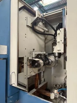
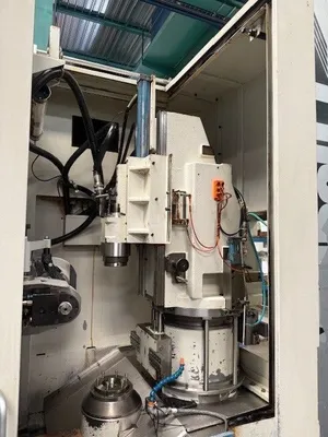
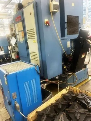
This 400 mm-class CNC hobber carries forward the Gleason legacy of rigid construction and forward-looking engineering. High-speed capability, robust castings, and modern design principles give it the backbone to fully exploit today’s—and tomorrow’s—cutting tool technology. The PHOENIX 400GH keeps its footprint compact without compromising rigidity, accuracy, or serviceability, and its use of standardized, globally supported components helps ensure quick delivery, lower maintenance, and minimal spare-parts burden.
Built-in thermal stability and Gleason’s mature CNC software platform deliver excellent accuracy and repeatability while keeping operating costs in check. The machine supports both wet and dry hobbing and handles high-speed steel or carbide tooling with ease.
Gleason’s CNC hobbers have long been benchmarks in the industry; the 400GH builds on that lineage. It’s engineered for straight spur and helical gears, pinions, splines, worm gears, and similar profiles up to 400/450 mm (15.75/17.72 in) diameter, 525 mm (20.67 in) face width, and 2.5 DP capability.
The machine features a functional ring loader with load / unload door to the right of the operator station. Machine Tool Builders can configure a new conveyor, lifting station and alter the enclosure to suit all of your requirements.
Gleason PHOENIX 400GH — Controls Retrofit Program Description & Consolidated Specification Sheet:
1 All work will be done at MTB facility in Machesney Park, IL.
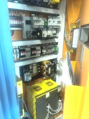
2 The machine will be fully re-controlled with a new CNC, new drives and servo motors, and a new electrical cabinet.
MECHANICAL:
3 Engineer as required then manufacture and supply all motor adaptation flanges, couplings and pulleys.
4 Remove old servo motors and install new servo motors.
5 MTB will check and report on all axes positioning and performance.
6 No mechanical repairs will be undertaken unless required to complete the recontrol. Should MTB identify any mechanical issues during the recontrol we will bring them to your attention and a course of action can be determined at that time.
HYDRAULIC:
7 MTB will interface the new CNC/PLC with the existing hydraulic system. However no hydraulic system modifications will be undertaken unless required to complete the recontrol.
LUBRICATION:
8 MTB will interface the new CNC/PLC with the existing lubrication system. However, no lubrication system modifications will be undertaken unless required to complete the recontrol.
COOLANT:
9 MTB will interface the new CNC/PLC with the existing coolant system. However, no coolant system modifications will be undertaken unless required to complete the recontrol.
CHIP EXTRACTION:*
10 MTB will configure this machine with a chip basket. A Chip conveyor can be quoted at additional expense - please advise.
ELECTRICAL:
11 A new operator’s panel.
12 All new secondary encoder cabling will be run for encoders we need to replace.
13 Machine wiring which is not directly a part of the recontrol or retrofit will be reused, and connected via terminal strips within the new panel.
14 MTB will provide all wire, tags, conduit, flex and other miscellaneous equipment required to complete the installation per NFPA codes.
15 All electrical prints and parts lists will be drawn with AutoCAD Electrical.
15 All new servo motor power and feedback cables will run.
16 Cabinet will remain in the current location
17 Power requirements will be 480VAC; 60Hz. Power figures will be available after the electrical engineering is completed.
CONTROLS:
18 Fanuc 0iF Plus CNC
19 Fanuc 10.4” Color LCD touch screen display unit
20 Fanuc drives and motors
21 ATTENTION – If your plant power system is not a wye scheme with grounded center point, you will require an isolation transformer for these new drives.
DOCUMENTATION:
22 Two (2) copies of the wiring diagrams on 11x17 paper. Per machine.
23 Two (2) copies of the MTB operators Instruction manuals. Per machine.
24 Two (2) copies of spare parts and service manuals for equipment supplied by MTB. Per machine.
25 Two (2) copies of the PLC logic interface program and backup USB. Per machine.
26 Two (2) copies of any mechanical prints for changes which MTB makes during the recontrol / retrofit / rebuild. Per machine.
27 One (1) copy of the Fanuc CD for the CNC and drives.
INSTALLATION & RUNOFF:
28 Customer to provide assistance with installing of the recontrol package with but not limited to cranes, forklift, ladders, etc.
TRAINING:
29 MTB will supply training at additional charge based upon customer specifications as part of sale.
BUILD SPECIFICATIONS:
30 Electrical, mechanical, hydraulic, pneumatic and safety systems will be installed in accordance with all applicable customer specifications, and ISO, IEEE, ANSI, DIN and NFPA standards.
MACHINE DESCRIPTION — INCH / ENGLISH — METRIC
CAPACITY & RANGE:
Maximum workpiece diameter — with carousel* 15.75" 400 mm
Maximum workpiece diameter — manual load 17.72" 450 mm
Maximum part weight (carousel)** 125 lbs 56 kg
Max diametral pitch / module (standard 100–1000 RPM) 2 NDP 12 module
Max diametral pitch / module (optional 150–1500 RPM) 2.5 NDP 10 module
Maximum hob spindle torque 2500 in-lb 280 Nm
Maximum hob setting angle ±45° ±45°
Total swivel motion –165° / +45° (210°) –165° / +45° (210°)
Minimum number of teeth 2 2
SPINDLE, TABLE & SLIDE GEOMETRY:
Center distance Hob → Workpiece (min) 1.38" 35 mm
Center distance Hob → Workpiece (max) 12.20" 310 mm
Height Work spindle → Hob center (min) 2.95" 75 mm
Height Work spindle → Hob center (max) 9.25" 235 mm
Axial hob slide travel 10.82" 275 mm
Radial slide travel 10.83" 275 mm
Work spindle → Tailstock face (min) 13.78" 350 mm
Work spindle → Tailstock face (max) 14.96" 380 mm
Work spindle mounting diameter (with adapter) 5.91"–12.60" 150–320 mm
Draw rod interface hole diameter 5.98" 152 mm
Work spindle bolt circles 5.91" & 7.48" 150 & 190 mm
Tapped holes M10 × 1.5 × 20 mm M10 × 1.5 × 20 mm
Max chucking force (hydraulic) 17,600 lbf 78.3 kN
HOBBING TOOLING & DRIVE:
Maximum hob diameter 6.25" 160 mm
Maximum hob length (tangential travel) 4.88" 460 mm (varies; 50 mm min)
Hob arbor diameters (Available, not necessarily present) 1.25" / 1.50" 32 / 40 mm
Hob spindle taper ISO 40
Hob spindle speeds — standard: 150–1000 RPM 150–1000 RPM
Hob spindle speeds — optional: 150–1500 RPM 150–1500 RPM
Low-speed range: 1–75 RPM
Optional low-speed: 15–150 RPM
FEED RATES, MOTORS & POWER:
Worktable speed 197"/min 5000 mm/min
Radial traverse rate 197"/min 5000 mm/min
Axial traverse rate 197"/min 5000 mm/min
Hob drive motor (6000 RPM, 15 Alpha) 20 HP 15 kW
Work spindle motor 10 HP 7.5 kW
Hydraulic unit motor 3 HP 2.2 kW
Coolant motor — high pressure 11 HP 8 kW
Mist collector motor 0.75 HP 0.6 kW
DIMENSIONS & WEIGHT:
Machine size 93" × 134" 2.36 × 3.40 m
Machine w/ carousel (approx.)** 198" × 206" 5.8 × 7.2 m
Net machine weight 26,200 lbs 11,884 kg
Net weight w/ carousel* 26,600 lbs 12,128 kg
FEATURES & EQUIPMENT:
• Machine-mounted, air-conditioned electrical enclosure with operator controls at front.
• Fully enclosed work area with powered operator access door and internal lighting.
• Smoke/mist collector interface.
• Self-contained coolant system with tank, pump, piping, magnetic chip conveyor.
• Cooler-chiller for both hydraulic and cutting oil circuits.
• Standard swivel hob head with FANUC 15 motor and quick-change hob clamping.
• One hob arbor (diameter specified by customer).
• Hydraulic workpiece chucking via draw-arbor.
• Support column & hydraulic tailstock arm with 180° swivel base for twin-gripper load/unload.
• CNC control of six axes:
– (A) - axial feed
– (X) - radial feed
– (Y) - hob position
– (S) - hob speed
– (C) - worktable
– (A) - swivel angle.
• Full electrics for 380V / 50 Hz.
• Complete machine documentation: manuals, parts list, hydraulic & electrical schematics.
*Chip Conveyor not included with this machine; chip basket only. We can quote a conveyor on request.
**Original Carousel is NOT included. We are able, however, to configure a new one and adapt it to suit your requirements.
***Original Carousel NOT included, but the weight requirements are typical and may well apply.
We use cookies to improve your experience. Privacy Policy.