


Used FELLOWS Fellows 10-4 Recontroled CNC | Gear Shapers
Have one to sell?
ConditionUsed
1 available
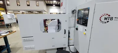
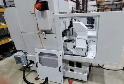
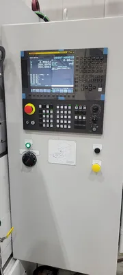
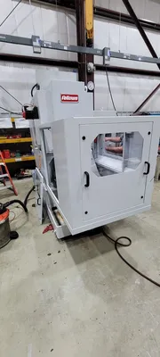
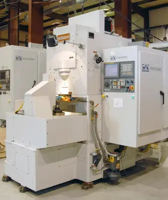
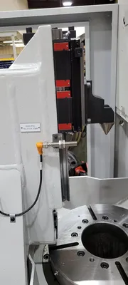
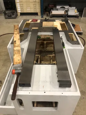
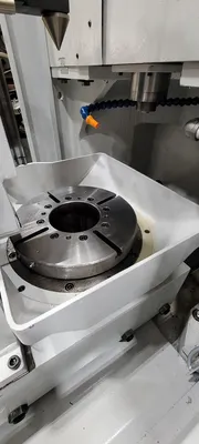
Machine Tool Builders is pleased to offer a recontrol of one Fellows 10-4 gear shaper from an existing Fanuc-controlled core machine provided to us for our work to begin in Machesney Park, IL.
The recontrol MTB is proposing will replace the existing system with a Fanuc 0iF + CNC. MTB will also be replacing the entire electrical cabinet and all the equipment and wiring inside of the electrical cabinet with new equivalents. This includes all motor starters, relays, power supplies, terminal strips, fuses etc. The machine will be recontroled to a 3-axis and single spindle CNC controlled machine. The existing drive systems will be replaced by new Fanuc Alpha iS HV digital servomotors and drives of the proper torque and speed. The spindle system will be controlled by a new Fanuc Alpha series spindle drive system. MTB will include, as part of the recontrol, our conversational programming which will provide your operators with menu driven part and process information on the CNC operator’s panel. This allows ease of entry of the gear data by the operator.
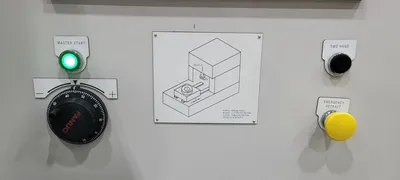
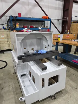
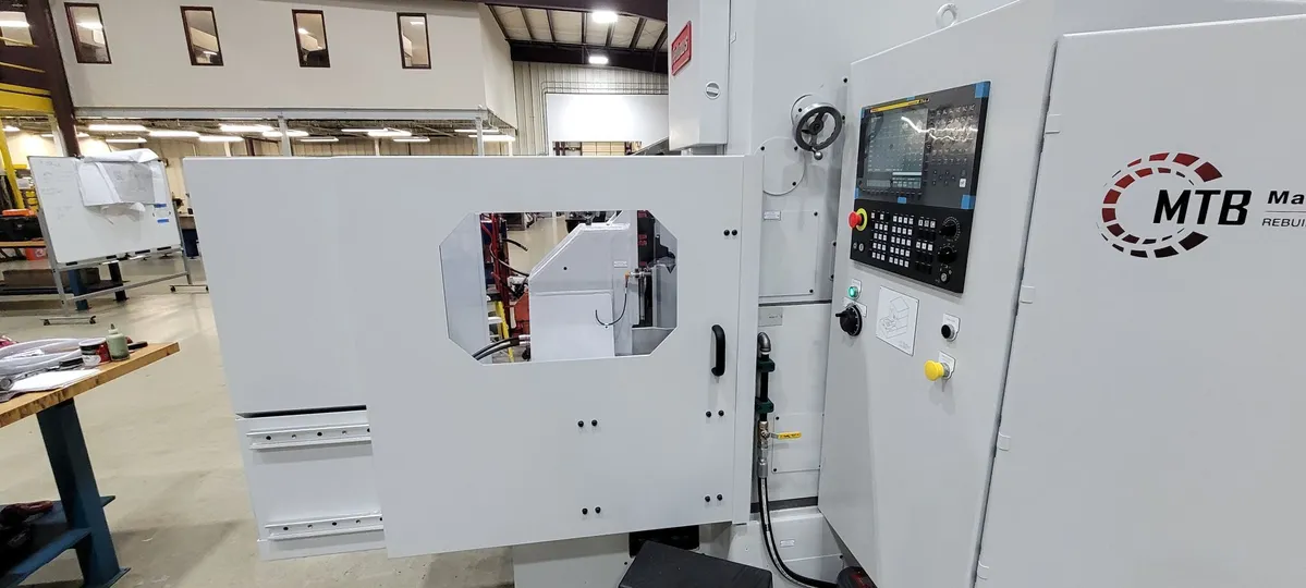
The pictures herein represent a machine currently in build that was actually converted from mechanical operations to CNC. As your machine may have already been converted to CNC some of the procedures listed herein may change or otherwise be altered. The pictures of a complete machine are representative of type only - having been the last machine we completed in late 2025. We expect to be able to complete a machine to this level in 4 to 5 months based on current order backlog.
We appreciate your considering Machine Tool Builders, Inc. for this project. If you have any questions regarding this quote, please feel free to contact us anytime.
Fellows 10-4 Shaping Machine Re-Control Program - 3 Axes of CNC Control. Specifications below are typical for type, but may differ slightly as a result of the condition & type of your model.
The following program is for a Re-Control of your existing Fanuc controlled machine, with the work to be done in Machesney Park, IL.
MTB will evaluate and address mechanical issues identified during the recontrol program on a case-by-case basis. Any mechanical deficiencies discovered during inspection or throughout the course of the work that fall outside the defined scope of this proposal may impact the ability to complete the recontrol as planned. Such conditions will be documented and communicated promptly, and any required corrective actions will be reviewed, quoted, and approved separately prior to proceeding.
I. MACHINE SPECIFICATIONS:
• Maximum workpiece diameter: 10” / 254 mm
• Maximum stroke length: 4” / 102mm (See Below for Add'l Options)
• Maximum Diametral pitch (spur): 4DP / 6.35 Module
• Maximum Diametral pitch (helical): 5DP / 5.08 Module
• Maximum strokes per minute: 750 SPM / 1,200 SPM (Optional)
• Maximum center distance workpiece/tool: 14” / 355.6 mm
• Distance between worktable and cutter: 13.0” / 320.2 mm
• Bore through work spindle: 5.875” / 149.225 mm
• Cutter spindle diameter: 3.543” / 89.998 mm
• Fanuc α15/7000 HVi spindle motor: 20 HP / 15 kW
• Rapid traverse rates:
- X axis: 118 in/min / 3000 mm/min
- B axis: 40 RPM / 14,400 deg/min
- C axis: 40 RPM / 14,400 deg/min
• Linear axis resolution: .0001” / .001mm
• Rotary axis resolution: .001° / .001°
• Plant power requirement: 460V 60Hz 3-Phase
• RS-232 port or up/down loading programs.
• PCMCIA port for up/down loading programs.
II. MACHINE RECONTROL FEATURES:
Item GENERAL
1). All work will be done at Machine Tool Builders facility located in Machesney Park, IL.
2). The spindle speed will be controlled through a new spindle drive and spindle motor.
3). The radial axis (X) will receive a NEW CNC controlled axis.
4). The cutter rotation axis (B) will receive a NEW CNC controlled axis.
5). The worktable axis (C) will receive a NEW CNC controlled axis.
6). The elevation will remain a manual adjustment.
7). The stroke length will remain a manual adjustment - (OPTION AVAILABLE See below).
GENERAL MECHANICAL:
8). Remove old servo motors and install new servo motors.
9). Remove old spindle motor and install new spindle motor.
ELECTRICAL:
10). A new electrical cabinet will be installed with all new equipment inside. IEC devices along with circuit breakers will be used wherever possible.
11). A new operator’s station will be installed where the current one is. It will include the CRT, Keyboard and Machine operation panel mounted inside.
12). Installation of all new CNC associated machine wiring.
13). MTB will provide all wire, tags, conduit, flex and other miscellaneous equipment required to complete the installation per NFPA codes.
14). All electrical prints and parts lists will be drawn with AutoCAD Electrical.
15). All new servo motor power and feedback cables will be run for only the replaced servos on the machine.
16). All new secondary encoder cabling will be run for only the replaced servos on the machine.
17). New cabling to the operator’s station or pendant will be run.
18). Unless otherwise stated all axes will be measured from absolute encoders within the servo motors.
19). Reuse any electrical cabinets, duct way and junction boxes that are practical to reuse, unusable ones will be replaced with new.
20). Power requirements will be 460VAC; 60Hz. Power figures will be available after the electrical engineering is completed.
III. ELECTRICAL & SOFTWARE:
CONTROLS:
21). Fanuc 0i-F+ CNC with 10.4" horizontally arranged color display and machine operator's panel.
22). Fanuc Alpha iS HV digital axes drive(s) and motor(s).
23). ATTENTION - If your plant power system is not a wye scheme with grounded center point, you will require an isolation transformer for these new drives.
SHAPING SOFTWARE:
24). Conversational based platform within the CNC.
25). Up to four sequential surfaces (Only practical if elevation setting is under CNC control).
26). Up to five cuts per cycle.
27). Spiral or Plunge infeed cycle.
28). Programmable rotary dwell.
29). Digressive infeed feedrate.
30). Inch / Metric switchable.
31). Spiral out of cut.
32). M and G code programming is allowed with conversational programming present.
33). Multiple program storage and retrieval.
34). Quick recut cycle - allows the operator to bring the workpiece into size without changing the programming parameters.
35). Auxiliary function selection (tailstock/clamping seq.).
36). Automatic cutter indexing (Requires independent cutter 'B' and worktable 'C' axes).
37). Orientation of cutter and workpiece (Requires independent cutter 'B' and worktable 'C' axes).
38). Clamp avoidance (Requires independent cutter 'B' and worktable 'C' axes).
39). Slotting capability (Requires independent cutter 'B' and worktable 'C' axes).
DOCUMENTATION:
40). Two (2) copies of the wiring diagrams on 11x17 paper.
41). Two (2) copies of the MTB operators Instruction manuals.
42). Two (2) copies of spare parts and service manuals for equipment supplied by MTB.
43). Two (2) copies of the PLC logic interface program and backup CDROM.
44). Two (2) copies of any mechanical prints for changes which MTB makes during the recontrol / retrofit / rebuild process.
INSTALLATION & RUN-OFF:
45). Installation, runoff and training at our facility in Machesney Park, IL. We can quote Installation, runoff and training at your facility for additional charge.
TRAINING:
46). MTB will supply 2 days of operator training at the completion of the installation.
47). MTB will supply 1 day of maintenance training at the completion of the installation.
BUILD SPECIFICATIONS:
48). Electrical, mechanical, hydraulic, pneumatic and safety systems will be installed in accordance with all applicable customer specifications, and ISO, IEEE, ANSI, DIN and NFPA standards.
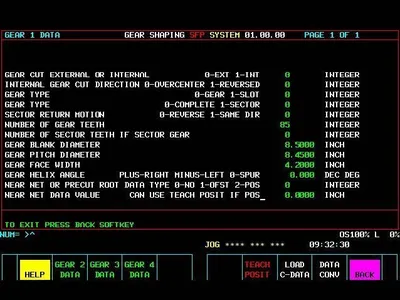
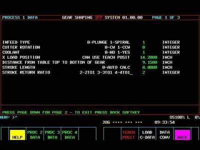
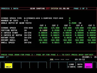
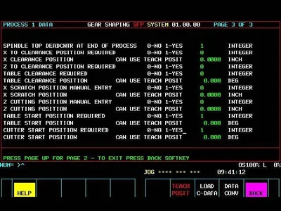
MTB's shaping conversation software for gear shapers is a Macro Executor based program running from the SRAM memory on the Fanuc CNC. The programming environment is made very user friendly through built-in help screens and helpful prompts. After entering the data for each respective item, you then create a program by selecting a cutter, a workpiece and a process from the items in the library. A program can consist of up to four surfaces that you want to cut.
Please see "Additional Photos" below for details on the HMI Screens.
We use cookies to improve your experience. Privacy Policy.