


2001 GLEASON PFAUTER P600/800 MTB Recontrolled 2018
Have one to sell?
ConditionUsed
1 available
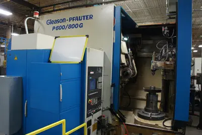
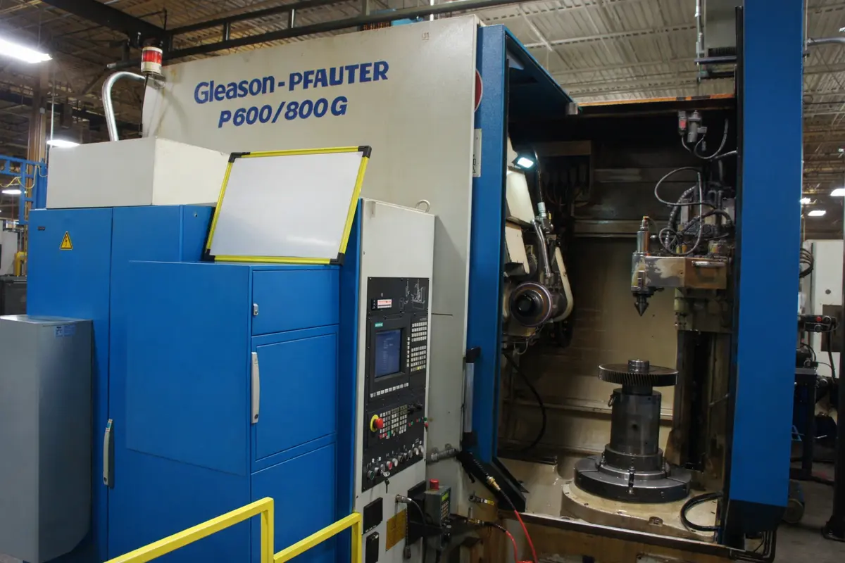
Gleason-Pfauter P600/800G CNC Profile / Form Gear Grinding Machine Recontroled by MTB in 2018.
This machine was recontroled in 2018 by the Machine Tool Builders team with a Siemens 840Dsl CNC Control with a PCU 50 (PC) Front End and a Windows 7 operating environment.
The current software on this machine was originally produced by MTB and features our legendary conversational programming format we are known for - that also facilitates the ability to program free-hand for specialized applications inherent in profile grinding. It is possible to update the software to MTB's latest version for a nominal charge (see below).
The entire controls cabinet was replaced at that time and the Gleason-Pfauter P600/800G is a CNC profile (form) gear grinding machine designed for high-precision grinding of external and internal spur and helical gears. Part of the medium-size P-Series platform, the P600/800G offers robust construction, high-accuracy axis control, and flexible dressing capability for demanding production and finishing applications. This machine also features an offset tailstock to facilitate loading of heavier workpieces from directly overhead.
The machine is currently under power and operational - but is slated as surplus to ongoing operations.
Machine Tool Builders Description Prior to Original Recontrol circa 2018:
This is the description below from that event - not current as this machine is classified as 'USED.'
This is a seven axis machine.
1. X (Depth)
2. Y (tangential)
3. Z (Axial)
4. C (Part rotation)
5. Z2 (Dresser depth)
6. A (Head Angle)
7. S (Grind Wheel Rotation)
8. S2 (Dresser Spindle)
General:
1 The machine will be recontrolled with a new CNC and new drives
2 X axis will receive a new servo motor
3 Y axis will receive a new servo motor
4 Z axis will receive a new servo motor
5 Z2 axis will receive a new servo motor
6 A axis will receive a new servo motor
7 C axis will receive a new servo motor
8 The dresser spindle will receive a new servo motor
9 The spindle motor will be reused, but controlled by a new spindle drive for speed
Mechanical:
10 Engineer as required then manufacture and supply all motor adaptation flanges, couplings and pulleys.
11 Remove old servo motors and install new servo motors
Hydraulic:
12 MTB will interface the new CNC/PLC with the existing hydraulic system. However no hydraulic system modifications will be undertaken unless required to complete the recontrol.
Lubrication:
13 MTB will interface the new CNC/PLC with the existing lubrication system. However no lubrication system modifications will be undertaken unless required to complete the recontrol.
Coolant:
14 MTB will interface the new CNC/PLC with the existing coolant system. However no coolant system modifications will be undertaken unless required to complete the recontrol.
Chip Extraction:
15 MTB will interface the new CNC/PLC with the existing chip extraction system. However no chip extraction system modifications will be undertaken unless required to complete the recontrol.
Wheel Balancer:
16 MTB will reuse any balancing system currently on the machine, and all related equipment for the balancing system.
Electrical:
17 A new electrical cabinet will be installed with all new equipment inside. IEC devices along with circuit breakers will be used wherever possible.
18 A new operator's control station will be installed in the side of the electrical cabinet.
19 All new secondary encoder cabling will be run.
20 Auxiliary cabinet lighting and programming terminal power will be supplied.
21 Machine wiring which is not directly a part of the recontrol or retrofit will be reused, and connected via terminal strips within the new panel.
22 MTB will provide all wire, tags, conduit, flex and other miscellaneous equipment required to complete the installation per NFPA codes.
23 Unless otherwise stated all axes will be measured from absolute encoders within the servo motors.
24 X axis will use a new Heidenhain absolute scale (No referencing required upon power up).
25 Y axis (Tangential) will use a new absolute scale (No referencing required upon power up).
26 Z axis (axial) will use a new Heidenhain absolute scale (No referencing required upon power up).
27 Z2 axis (axial) will use a new absolute scale (No referencing required upon power up) only if the axis is so equipped currently.
28 All electrical prints and parts lists will be drawn with AutoCAD Electrical.
29 All new servo motor power and feedback cables will run.
30 Cabinet will remain in the current location.
31 Hand held pendant with handwheel, axis select, dead man buttons, E-Stop button and coil cord.
32 Power requirements will be 460VAC; 60Hz. Power figures will be available after the electrical engineering is completed.
Controls:
33 Siemens Sinumerik 840DSL CNC.
34 Siemens Sinumerik OP 015A, 15" TFT color display operator's panel.
35 Siemens PCU50.5-C Celeron 1.8Ghz/4GB RAM Cache/400Mhz FSB; 40GB HD;2x Ethernet 10/100Mb (RJ45); 4x USB 2.0; 1x RS232C; 2x PCI slot; 1x Compact Flash; WIN7.
36 Siemens Sinumerik MCP483C Machine Tool Builders panel with E-Stop Button, Feedrate and Spindle Overrides, Security Key switch and Programmable Buttons.
37 Siemens Sinamics Digital Drives and Siemens Servo Motors.
38 ATTENTION - If your plant power system is not a wye scheme with grounded center point, you will require an isolation transformer for these new drives.
Software:
39 PC Based Conversational platform. Includes MS Windows based operator interface. Windows Operating Environment. Hard drive, Ethernet Port, USB port, Printer Port, Serial Port.
40 Auxiliary function selection (tailstock/clamping seq.)
41 Choice of Single or Multi Revolution Cycles. Single Rev makes multiple passes to depth then indexes. Multi Rev grinds all teeth at the same depth, and then indexes.
42 Crowning with crown offset. Includes true tapered crowning by coordinate system rotation.
43 CSS for dressable wheels.
44 Ground tooth memory. Allows restart on last unfinished tooth.
45 Helical or spur gear grinding.
46 Dressing cycles with profile, tip and root modifications that can be different on each side.
47 Inch / Metric switchable.
48 Internal grinding on either side of center.
49 M and G code programming is allowed with conversational programming present.
50 Multiple program storage and retrieval.
51 Non sequential indexing of workpiece.
52 Programmable skip tooth (up to 5).
53 Programmable Sparkout cycle.
54 Quick regrind cycle.
55 Selectable grinding passes; Same or Alternating.
56 Selectable grinding start directions.
57 Semi-Automatic alignment tooth routine.
58 Sizing cycle with selectable tooth for start. Grinds opposing teeth to depth then stops for measurement.
59 Taper correction.
60 Up to four grinding passes; Rough, Medium1, Medium2, Fine.
61 Wheel overspeed protection.
62 Selectable grinding plane X or Z.
Painting:
63 The electrical cabinet will be painted in the color of your choice, or to match the machine. Please specify with order.
Documentation:
64 Two (2) copies of the wiring diagrams on 11x17 paper.
65 Two (2) copies of the MTB operators Instruction manuals.
66 Two (2) copies of spare parts and service manuals for equipment supplied by MTB.
67 Two (2) copies of the PLC logic interface program and backup CDROM.
68 Two (2) copies of any mechanical prints for changes which MTB makes during the recontrol / retrofit / rebuild.
69 One (1) copy of the Siemens DOC on CD for the CNC and drives.
Installation and Run Off:
70 Installation and runoff at your facility.
Build Specifications:
71 Electrical, mechanical, hydraulic, pneumatic and safety systems will be installed in accordance with all applicable customer specifications, and ISO, IEEE, ANSI, DIN and NFPA standards.
Capacity (Typical Configuration):
Maximum workpiece diameter: approx. 600 mm (23.6")
Extended versions (P600/800G): up to approx. 800 mm (31.5")
Maximum gear face width: approx. 600 mm (23.6")
Maximum profile depth: approx. 35 mm (1.38")
(Certain variants reported up to ~80 mm depending on configuration)
Maximum pitch capability: approximately 1.5 DP (model dependent)
Axis & Motion Data (Typical Values):
X-Axis (Radial infeed) rapid traverse: approx. 10,000 mm/min
Y-Axis (Tangential movement): approx. 5,000 mm/min
Z-Axis (Axial travel): approx. 4,800 – 10,000 mm/min
Wheelhead swivel capability: approx. ±40° to ±45°
Grinding wheel speed range: typically 600 – 6,000 rpm
(Some configurations reported up to 8,000 rpm)
Workholding & Table:
Table diameter: typically approx. 450 – 800 mm depending on configuration.
Table speed range: approx. 0 – 14 rpm.
Tailstock support available on heavier duty configurations.
Suitable for both external and internal gear grinding.
Machine Dimensions & Weight (Approximate):
Floor space: approx. 6.2 m x 6.6 m x 3.7 m.
Machine weight: approx. 11,000 – 17,000 kg.
(Varies with options, coolant system, guarding, automation, etc.)
We use cookies to improve your experience. Privacy Policy.